SSB speech processing
Technical background:
A crucial factor of SSB operation is the way of speech processing. This can be proven by displaying a microphone output signal by means of an oscilloscope. Even a skilled operator rarely will obtain a dynamic range of less than 6 db between the maximum and minimum of the output amplitude. Usually, this range will be 40 db or even more. But decisive for the effective output power of a transmitter is the mean drive, which will be, at least, 6 db below the pep („ideal“) or („typical“) up to 40 db below the peak.
A practical example:
Imagine a power amplifier designed for 10 W pep driven by a mean ssb signal, which at least will be down by 6 db below the peak. This means a minimum output power of 2.5 watts and a resultig S meter reading of one step down from the peak. Equalizing the dynamic range of the modulating signal will result in a better effectivity of the power amplifier as this will raise the „mean“ output power. Even if this might not be directly visible at the receiver S meter, the compression of the dynamic range will increase the readability and the SNR at the receiving side. In practice, it could be proven that a – moderate – clipping limit of 20 db virtually simulates an 80 watts transmitter while, in reality, the pep output is only 10 watts. Thus, after switching on the clipper, the typical question of the partner operator will be, which type of additional power amplifier you are using now.
Let us now discuss, in short, the three mostly used methods of speech processing.
The AF Compression:
Within the AF (microphone) amplifier all amplitude peaks are compressed in order to minimize the variations caused by the way the operator talks. Technically, this compression is realized by an automatic gain control, which keeps the output level constant regardless of the fluctuation of the speaker’s voice level. The need of a certain control time constant makes it nearly impossible to eliminate the resulting distortions. Additionally, this time constant has to be adapted to the operator’s personal voice characteristic.
The AF Clipper circuit:
Clipping the amplitudes of a voice signal results in a more uniform drive to the transmitter. Consequently, low-level syllables approach the level of the high-level ones. A clipping factor of 4, e.g., may improve the SNR (at the receiving side) by 12 db. Empirical test show that a 24 db improvement is the upper limit with the af clipper, before the signal degenerates to a rectangle with its unbearably high harmonic content and the resulting distortion. And, as the typical voice signal represents a wide spectrum of frequency components, these harmonics will mix down to heavy intermodulation, thus reducing the readability even more.
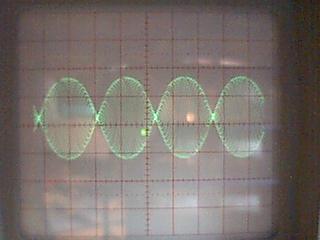
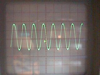
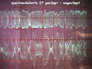
The RF Clipper circuit:
After mixing the voice signal to a rf signal, the result can be clipped and filtered against harmonics and intermodulation products, which fall outside the filter’s response. Finally, this processed signal is demodulated and then available as a dynamically compressed af signal.