2a.) RF Speech Clipper into Yaesu’s MH-31.
![]() <–WEB-Shop–>
<–WEB-Shop–> ![]()

GENERAL: The general function of RF Clippers has been described on my web site; here I want to drop some words on the particularities of the RF Clipper for the FT-817 and the ideas behind it. The first question was whether to develop an external or an internal (built-in) module. In order not to change the overall character of the FT-817, I decided to develop an external unit. Moreover, it had to be easy, even for a less skilled OM, to build it up without permanent modifications of his equipment. The only feasible solution turned out to be a module fitting into the case of the hand microphone. To make room for the clipper module, the microphone capsule itself had to be exchanged by a less bulky one. Some time ago, I developped a „Mini Clipper“, which earned very favourable critics by Hams who integrated it into their hand microphone without any shielding; no problems, at all, were reported even at transmitter output powers of up to 400 watts. The new FT-817 RF Clipper, therefore, is based on that design. The transceiver supplies a regulated voltage of 5 volts (DC) through its microphone connecting cable, which can be used to supply the clipper module. The basic i.f. clipping circuit is identical to that of the PEP model. I, as well as several other hams, use it successfully (see also: HAM Reports); the effective gain, compared to an unclipped signal, is at least 10 decibels. Before you can build the clipper module into the microphone case, you have to exchange the microphone capsule. I recommend to read the instructions below very carefully. With some skills in soldering, you will certainly be successful. The clipper module may also be built into a desk microphone without much problems. Be aware that, if the available supply voltage exceeds 8 volts it has to be reduced by means of a stabilizer 78L06! Some of the pictures here still show the first version of the clipper module with the „old“ blue filters. In the meantime, these have been exchanged by better ones. The electret mike capsule now is an integral part of the module (soldered directly on top of the pc board). Optionally, the electret mike may be replaced by the Heil model HC-4; the model HC-5 of Heil would be too large to be integrated into the MH-31 without major mechanical redesign! The clipper module also has been prepared to be operated from a dynamic microphone (not part of the module!); you then have to mount an extra transistor (included) on the pc board. There is no need to realign the module, in this case.
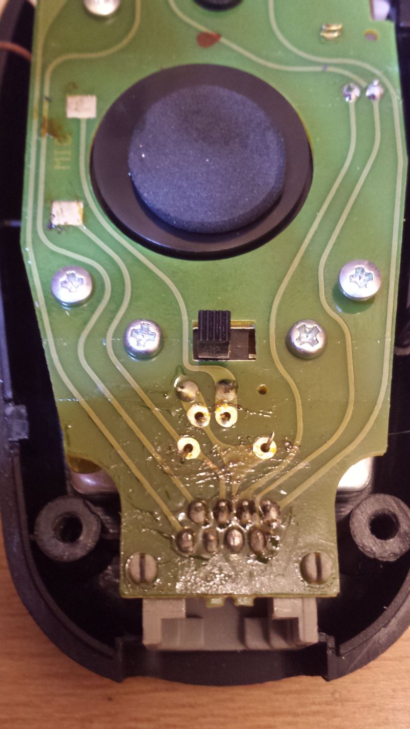
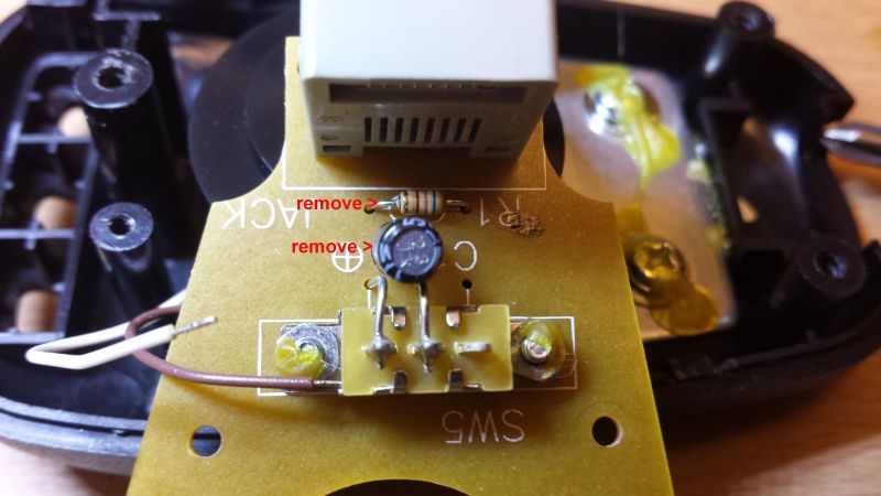
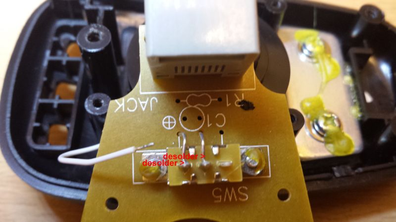
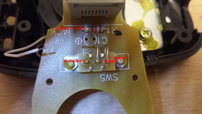
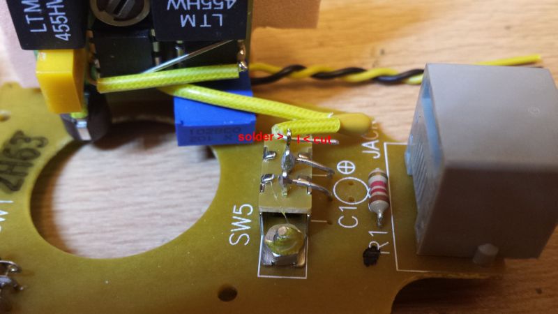
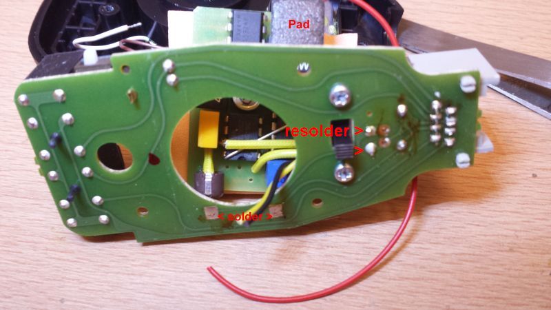
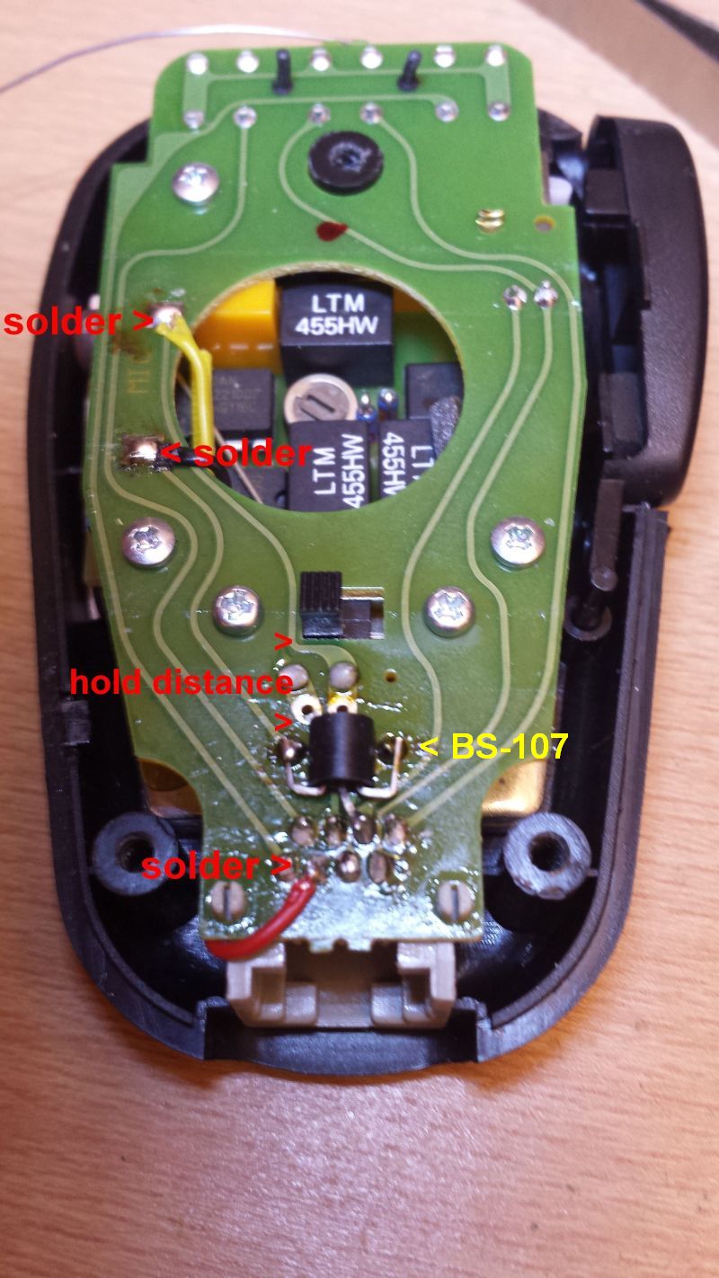
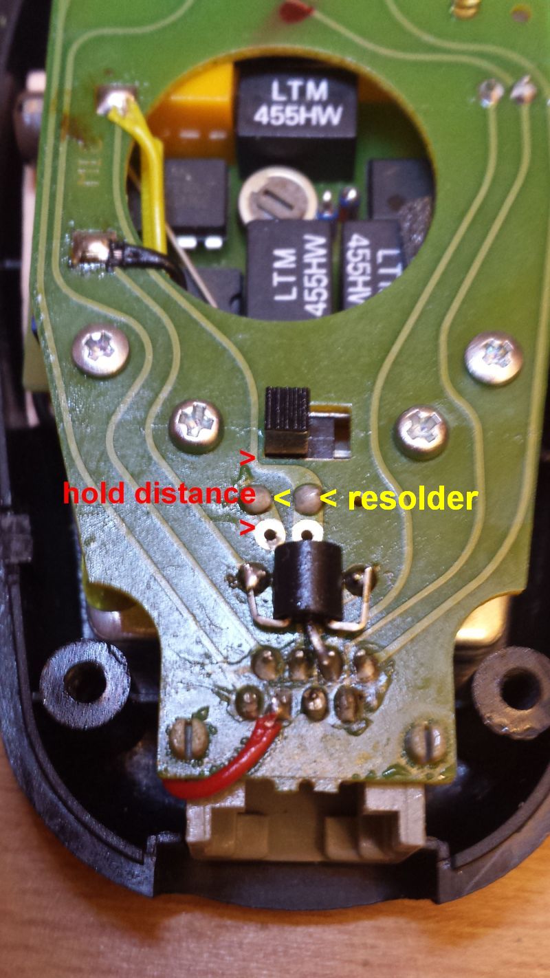
THE INSTALLATION: As a free-of-charge service, I offer the installation of the clipper module into the case of the MH-31. Just send me your microphone together with an address label; do not forget the return postage. The completed unit will be sent back on the next following working day. Now let’s have a look on the way how to install the clipper. Open the back cover of the MH-31 by loosening the screw (you need a philips screw driver). Then dissolder the wires to the microphone capsule. Dismantle the pc board by loosening the three screws and set aside the dynamic mike capsule. For the following steps, place the case in front of you so that the cable opening is nearest to your own body; the ptt key then is on the right side. Place the clipper module into the round hole (this was the space for the dismantled mike capsule); the level trimmer of the clipper module must look to the left side. Make sure that the round foam seal of the electret mike capsule is placed within the sound opening of the mike case. Draw the wrapped connecting wires of the clipper module through the round hole of the pc board and fasten them. Referring to the drawing below, shorten the wires and solder them. Very carefully solder the single heavy wire (power supply!) to pin #6; check for probable short circuits to the other pins. The clipper module as delivered normally needs no further alignment. If necessary, you now may set the clipping level and the frequency of the BFO in order to „individualize“ your clipper module. Finally, close the microphone case by means of its cover. During the individual set-up of the clipper, observe the ALC read-out of the FT-817; if necessary, set it according to the guide-lines of Yaesu. The frequency of the clipper’s BFO can be adjusted within a range of about ± 500 Hz; it determines the „pitch“ of your voice. Additionally, you may set the clip level and the a.f. output level of the clipper module. The clipper may be switched on or off by means of the „Tone Switch“ at the rear. A detailed description is included.

How to install: